Process
Valve Actuator Mounting Kits: How We Build Them, From First Measurement to Final Fastener
July 8, 2026
A detailed look at how valve actuator mounting kits are actually built — from working off drawings or field measurements through SolidWorks modeling, keyway broaching, and a complete fastener package. Ten years of this work, explained.
What Is a Valve Actuator Mounting Kit?
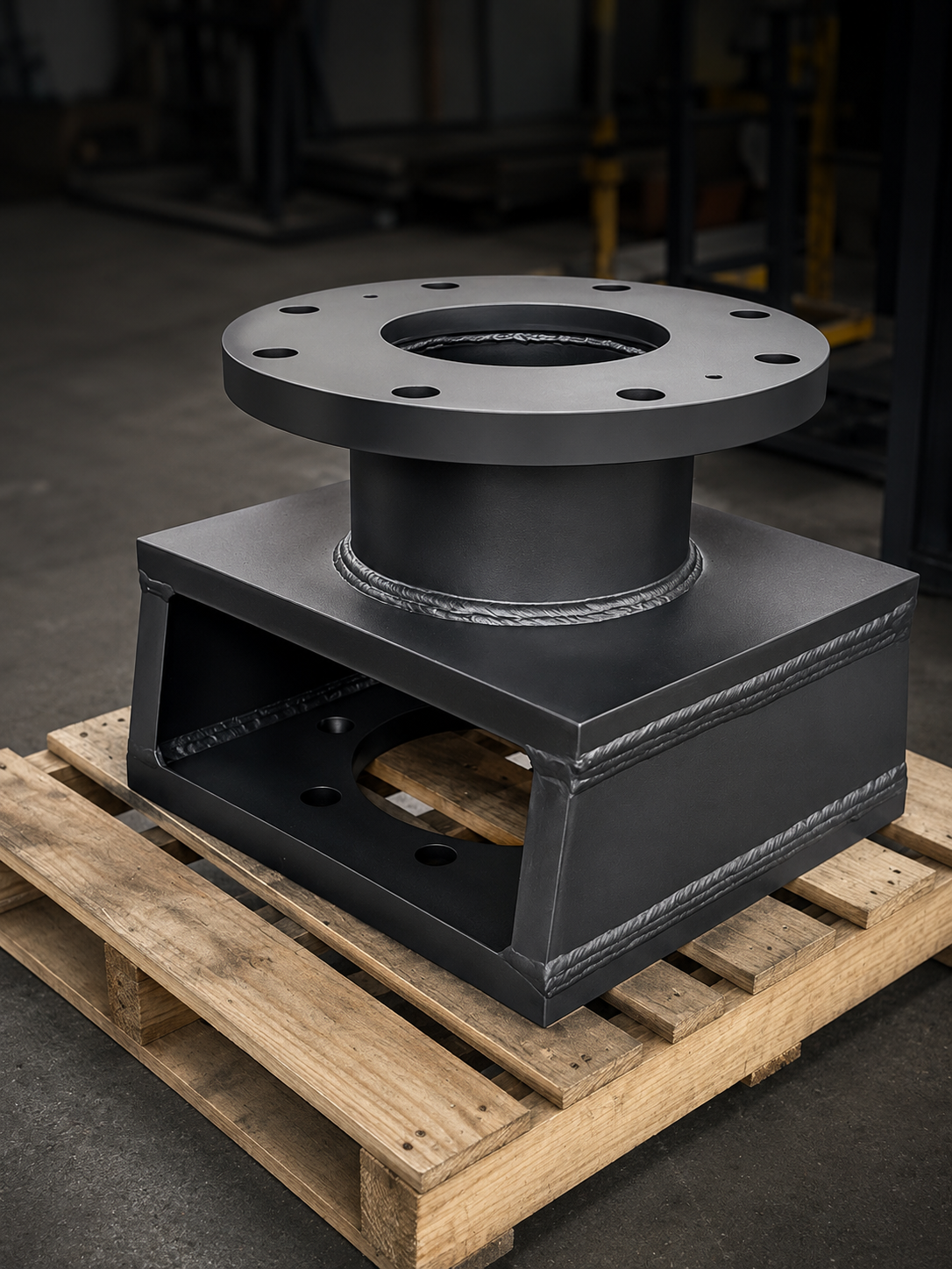
A valve actuator mounting kit is the mechanical interface between a valve and the actuator that operates it. At its core, a kit has three components: a bracket, a coupler, and a fastener package. The bracket bolts to the valve yoke or body and provides a mounting face for the actuator. The coupler transmits torque — or linear force — from the actuator's output shaft to the valve stem. The fasteners hold it together, and selecting the right grade, length, and clearance matters more than most people expect.
We have been building these kits for over ten years. What follows is how we actually do it.
Starting Point: Drawings, Hardware, or Field Measurements
Every kit begins with geometry. We need precise dimensions on two things: the valve's mounting face and stem, and the actuator's mounting face and output shaft. How we get that information depends on the job.
When drawings are available: We work from the valve manufacturer's dimensional drawings and the actuator manufacturer's installation drawings. Most major OEMs publish these; discontinued or older models can be harder to find. Over ten years of jobs, we've built a substantial internal library of valve and actuator reference drawings — when a repeat configuration comes in, we often already have the data.
When hardware is available but drawings aren't: The valve and actuator come into our shop and we measure directly. This is often faster than chasing paperwork and eliminates transcription errors.
When neither is available: Field measurement. We've developed our own measurement sheets — dimensioned diagrams of valve faces and actuator mounting patterns that a technician can fill in with a set of calipers. We have separate templates for quarter-turn valves (ball, plug), linear valves (globe, gate), and gear-operated configurations. The fields we need are highlighted on the PDF. A field person with basic measuring tools and our sheet can provide what we need.
Modeling the Assembly in SolidWorks
Once we have the geometry, every kit is modeled in SolidWorks before metal is cut.
This isn't a formality. SolidWorks lets us:
- Detect interference between the bracket, coupler, valve body, and actuator before anything is machined
- Animate the assembly to verify clearance through the actuator's full stroke
- Generate dimensioned shop drawings that go directly to machinists — no interpretation needed on the floor
The coupler is the most geometry-sensitive component. It must mate with two different bore profiles — valve stem on one end, actuator output shaft on the other — and transmit the actuator's full rated torque without slipping, binding, or deflecting. Every coupler is modeled and verified before cutting.
On large brackets and assemblies, we also run finite element analysis internally before signing off on the geometry. We do this for our own confidence — to verify that a large actuator won't deflect in a way that's visible or unsettling to operators in the field. We don't publish this or provide it as a customer deliverable. It's one more internal check we run to satisfy ourselves that what we're shipping will behave the way we intend.
Keyways: Where Valve Work Differs From General Machining
Valve keyways are not standard. General-purpose shaft-to-keyway size charts give the wrong dimensions for valve applications. Valve stems use oversized keys relative to bore size compared to standard mechanical practice. This is an industry-specific norm that catches shops without valve experience.
We cut internal keyways by broaching on our vertical CNC mills — a capability we developed entirely in-house. The tooling required to cut valve-specification keyways doesn't exist off the shelf, so we built it: custom tooling, custom fixtures, and CNC macros that handle the broaching cycle automatically. The result is a repeatable, controlled operation that produces consistent keyway geometry to our in-house tolerance standards — without requiring a dedicated broaching machine.
We have in-house tolerance standards for key fit: defined clearances on both the key depth and the width. These came from years of field feedback. A key fit that's too tight seizes under cyclic torque loading. One that's too loose fretts and damages the bore over time. We haven't had a dimensional callback on a kit that left our shop to our specification.
Verifying the Numbers
Before any bracket or coupler goes to the shop floor, we run it through a set of mechanical reference checks: key shear capacity, coupler torsional load, estimated deflection. These checks are based on published formulas widely used across the valve and actuator industry — the same reference standards major OEM actuator manufacturers use when specifying their own hardware. We're not performing an engineering analysis — we're checking our arithmetic before we commit to cutting material. If something doesn't look right at that stage, we modify the geometry and check again. It's a step that takes time, and one that not every shop bothers with.
Materials and Finish
Default materials are low-carbon mild steel for brackets and structural-grade steel for couplers. Both machine cleanly and meet the requirements of most applications.
On customer request, we've supplied kits in stainless steel (304 or 316 for corrosive or wash-down environments), aluminum (where weight is a factor and torque loads allow), and alloy steels for high-torque or elevated-temperature service.
Standard finish: brackets are painted flat black. Couplers ship bare. Where corrosion protection is required, we can supply zinc plating or coordinate other treatments through our supplier network.
MTRs on bracket and coupler material are available when specified at the quoting stage.
The Fastener Package
Every kit ships with a counted, labeled fastener package: the exact bolts, studs, nuts, and washers for the job, bagged and tagged with our job number and the customer's purchase order. For kits shipping to remote sites where assembly might happen weeks later or by a different crew, labeled bags prevent mix-ups.
Hardware grades are specified based on the actuator's rated torque and joint geometry — Grade 5 or Grade 8 imperial for most North American-origin actuators, metric for European-origin equipment.
One fit detail worth noting: the bolt hole clearance in the bracket-to-actuator flange joint. Enough clearance to let an assembler find alignment without fighting the hardware; not so much that the bracket can shift under cyclic loading. We've standardized this from experience.
What Drives the Work
New builds are the most common application: a skid package, a plant expansion, or a refinery upgrade where valves and actuators are going in new and need a matched mechanical interface.
Actuator type conversions are increasingly common across Alberta and the broader upstream sector — and the regulatory and financial pressure behind this shift is real.
Alberta's AER Directive 060 and Directive 017 regulate pneumatic devices — equipment that uses compressed natural gas to operate valves and pumps in upstream operations — and require facilities to measure and limit venting from these devices, with emission limits that came into force January 1, 2023. At the federal level, Canada's enhanced methane regulations (finalized December 2025 — Canada.ca) target a 72% reduction in upstream oil and gas methane emissions from 2012 levels by 2030, with provisions that effectively prohibit routine venting from pneumatic controllers by 2028.
The financial incentives match the regulatory direction. Emissions Reduction Alberta's Methane Reduction Deployment Program offers up to $2 million per company — covering up to 50% of eligible project costs — for upstream and midstream facilities delivering measurable methane reductions. The program runs until March 2029. ERA has already funded projects including electric valve actuator pilots tested at Alberta well sites and solar-hybrid power systems designed to replace pneumatic devices at remote locations running on well gas.
Converting from gas-operated pneumatic actuators to electric or solar-electric units is one of the primary technical responses to these requirements. We build the mechanical interfaces that make these conversions possible: the brackets, couplers, and linear drive assemblies that connect a new electric actuator to a valve that wasn't originally specified for one.
Retrofit and positioning applications are the work we find most technically interesting. This includes mounting position indicators on existing actuators, adding position feedback to gear operators, and building bracket solutions that use existing valve hardware without modification.
On a recent job: a quarter-turn lever-operated valve needed a position indicator added, but the lever had to remain fully functional for manual operation. We developed a C-shaped bracket that attached using existing holes in the valve body — no new drilling anywhere — and a riser coupler that the lever fit over. The coupler was stabilized by the bracket itself so the lever operated exactly as the original manufacturer intended, while the position indicator had a solid, accurate drive. The assembly was a complete retrofit that left the valve in its original certified condition.
What We Ship
A complete kit includes:
- Bracket(s)
- Coupler
- Labeled fastener package
- Our job number, traceable to our internal drawing file, material records, and job history
Assembly drawings and exploded views are available on request. Most crews who work with actuator mounting kits regularly don't need them — the hardware is self-describing. For less experienced crews or complex multi-piece assemblies, we can provide a SolidWorks-generated assembly view.
Requesting a Kit
To quote a valve actuator mounting kit, we need:
- Valve make, model, and size (or dimensions if no drawing is available)
- Actuator make, model (or dimensions if no drawing is available)
- Coupler bore profiles at both ends: valve stem and actuator output shaft (keyway, double-D, square, spline — specify both ends)
- Material specification, if other than mild steel
- Surface finish requirements
- Quantity
If drawings aren't available, contact us — we'll send the appropriate field measurement sheet for your valve type.
LET'S BUILD TOGETHER
Ready to start your next project?
Get a quote with full material traceability and documentation from day one.